GAUGE PROTECTION
To maintain instrument accuracy and protect diving personnel, all pressure gauges must be safeguarded against over-pressurization. System architecture relies on two key defensive components: pressure limiting devices and gauge isolation valves. When a gauge experiences pressure beyond its rated range, the internal Bourdon tube undergoes permanent plastic deformation. This destroys the instrument's calibration linearity, causes immediate failure during periodic recertification, and renders the gauge unfit for service. Installing pressure limiting valves automatically isolates the sensing element during unexpected pressure surges, while dedicated isolation valves allow technicians to safely remove, service, or test instruments without interrupting live dive operations or exposing low-pressure indicators to high-pressure manifold testing.
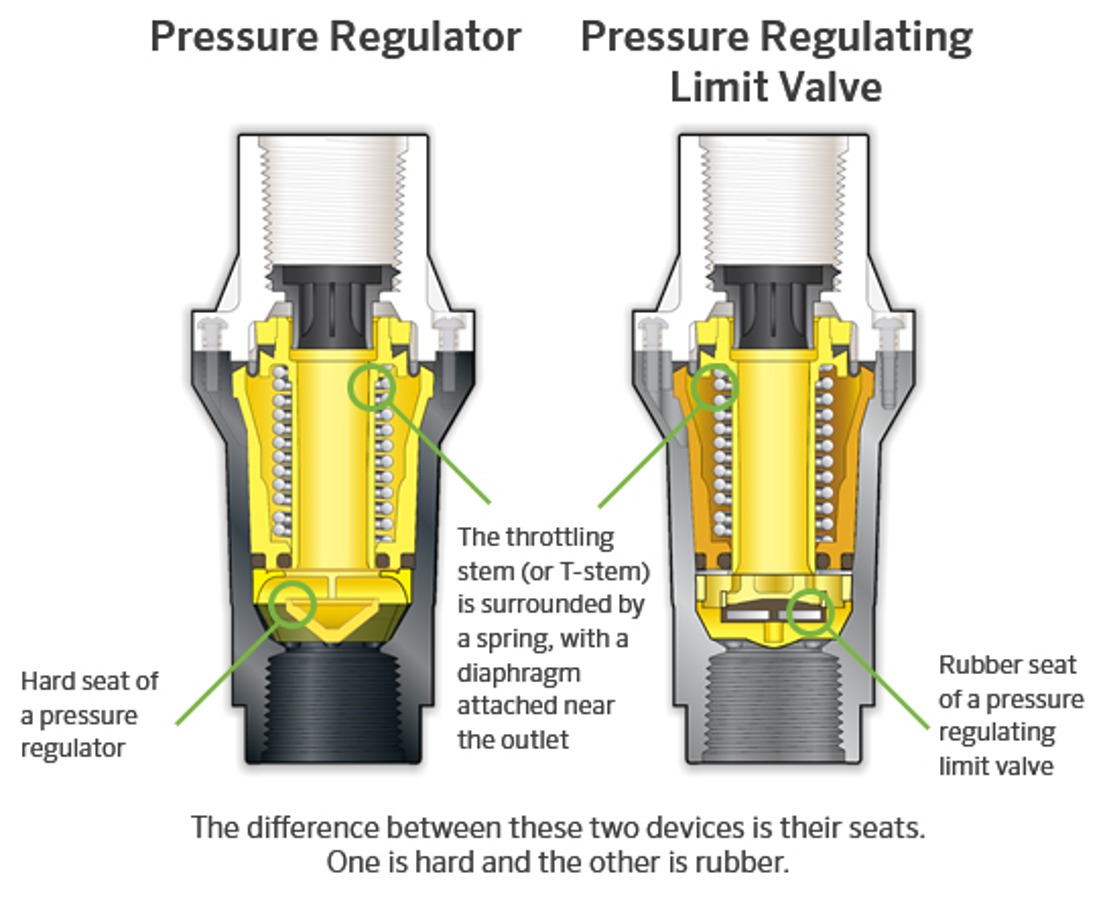
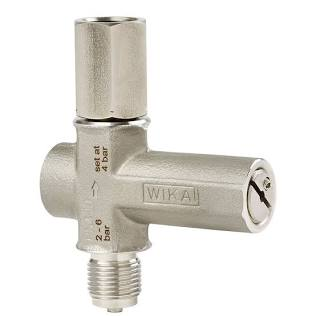
Pressure instrumentation deployed in Dive Control and life-support gas distribution systems must be shielded from mechanical shock, hydraulic/pneumatic spikes, and sustained over-pressurization. System design incorporates dedicated protective hardware to ensure measurement fidelity, personnel safety, and regulatory compliance.
Primary Protective Devices & Operational Functions
Pressure Limiting Devices (Overpressure Protectors):
Mechanism: Spring-loaded shutoff valves installed immediately upstream of the gauge.
Function: Automatically isolates the gauge sensor element when system pressure exceeds a predetermined threshold, reopening automatically when line pressure drops to safe operating levels.
Application: Essential for low-pressure (LP) and medium-pressure gauges situated downstream of pressure-reducing regulators subject to potential creep or seat failure.
Pressure Relief Valves (PRVs):
Mechanism: Calibrated mechanical relief mechanism set to crack at an engineered safety limit.
Function: Vents excess gas to atmosphere to prevent downstream system pressure from exceeding maximum allowable working pressures (MAWP).
Gauge Isolation Valves (Needle / Block Valves):
Mechanism: Fine-metering or quarter-turn shutoff valves positioned between the process line and the gauge inlet.
Function: Permits manual isolation of individual instruments without depressurizing the entire supply manifold or interrupting diver gas delivery.
Application: Used during instrument change-out, zero-point verification, routine maintenance, or to isolate vulnerable operational gauges during high-pressure system hydrostatic testing.
Metrological & Mechanical Impact of Over-Pressurization
Over-pressurization severely degrades the internal elastic sensing mechanism—predominantly the Bourdon tube, diaphragm, or capsule assembly. Subjecting an instrument to pressures beyond its maximum rated scale creates critical failure modes:
Plastic Deformation (Permanent Set): Exceeding the elastic limit of the Bourdon tube causes permanent elongation. The internal pointer shifts permanently off zero and cannot return to true datum.
Non-Linear Linearity & Hysteresis Errors: Overstressed internal linkages introduce severe measurement divergence between ascending and descending pressure readings.
Calibration Test Failure: A deformed sensing element fails statutory recalibration tolerances (typically $\pm0.25\%$ to $\pm1.0\%$ of Full Scale Deflection), requiring immediate condemnation and disposal of the gauge.
Rupture & Personnel Hazard: Severe over-pressure risks Bourdon tube fracture. Without safety blow-out backs or laminated viewing windows, this can result in catastrophic casing rupture inside the Dive Control van.
There are no comments for now.
to be the first to leave a comment.